Arduino Basics
Uno R3 Plus Board Not Included
Discover Arduino through EASY and FUN lessons
Step-by-step instructions with diagrams
No prior electronics knowledge required
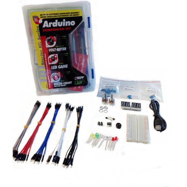
Kit comes with everything you need to build your own:
Volt Meter
LED Game
Buzzer Circuit and play melody
Arduino Starter Kit Includes:
6 feet USB type A to mini-B 1
Tact push switch 6mm x 6mm � through hole 2
DIP switch 4 position � through hole 1
1Kohm potentiometer (variable resistor) � long pins 1
10Kohm potentiometer (variable resistor) � long pins 1
330 ohm axial resistor, 1/2W, 5% 20
1 kohm axial resistor, 1/2W, 5% 5
10kohm axial resistor, 1/2W, 5% 5
LED through hole � Red, 8.7mm height, ~2V drop, ~10-20mA 2
LED through hole � Yellow, 8.7mm height, ~2V drop, ~10-20mA 2
LED through hole � Green, 8.7mm height, ~2V drop, ~10-20mA 2
LED through hole � White, 8.7mm height, ~2V drop, ~10-20mA 2
LED through hole � Blue, 8.7mm height, ~2V drop, ~10-20mA 2
Two digits 7-segment LED � RED 2
Buzzer, 5Vo-p 1
NPN transistor 2
Breadboard � 30 columns x 14 rows (include 2 VCC and 2 GND) 1
Ribbon Jumper Cables 40
9 Volt Battery Connector 1
2cm x 2cm x 3mm thick double side tape 2
Information sheet � Arduino UNO diagram + basic electronic theory 1
Kit container
Learning Center:
Attention Mac Users:
Please visit the following link to download the proper FTDI VCP driver before use:
http://www.ftdichip.com/Drivers/VCP.htm
Instructions below are written with the Uno R3 board.
I � Stuffs that you will need:
You will need a UNO R3 board, a mini USB to standard USB cable and Windows PC. The UNO R3 board will be powered by your PC through the USB cable, so don�t need a power adapter.
UNO R3 Mini USB to Standard USB Windows PC
II � Download the Arduino Environment:
III � Connect the Board to Your PC
a) Attached the USB cable to the mini USB connector on the UNO R3 Plus board.
b) Attached the other end of the USB cable to your Windows PC.
c) Windows will begin its driver installation process, but the process will fail. This is normal because Windows doesn�t natively carry the required FTDI Virtual COM port driver.
IV � Install the FTDI Virtual COM Port Driver:
a) Go to Control Panel then to Device Manager.
b) Under Port (COM & LPT), you should see the �FT232R USB UART� device with an �!� mark.
c) Right click on it and select �Update Driver Software�.
d) Choose the �Browse my computer for Driver software� option.
e) Navigate to the �drivers/FTDI USB Drivers� folder inside the arduino-x.y.z-windows folder you unzipped in step II.
f) Let Windows finish the installation.
V � Start the Arduino Environment and Upload your Sketch
a) Go back to the arduino-x.y.z folder and double click the arduino.exe file. The below Windows will appear.
b) Load the blinking LED example sketch by clicking �File → Examples → Basics → Blink�, and another Windows with the Blink sketch will appear.
c) Select your board by clicking �Tools → Board → Arduino UNO�. (IMPORTANT: If your sketch does not load properly using this selection, please select Arduino Duemilanove or Nano w/ ATmega328. It was brought to our attention that some of our UNO R3 boards may have been loaded with this bootloader instead (we are embarrassed). Functionally, it is the same so no real concerns. Please accept our apologies!! If you have any concerns, please email Support@osepp.com and you will be looked after!)
VI � Blinking LED Sketch
At this point, the LED labeled L on your board should be blinking ON and OFF. The LED should light ON for 1 second and OFF for 1 second.
You can experiment with the sketch and see how it alters the behavior of the LED. For instance, try changing the delay(1000) to delay (2000) or changing delay(1000) to delay(500).
Useful Note: A typical Arduino sketch consists of two main procedures, a �setup� functions and a �loop� procedure. The �setup� function gets executed one time only every time the board is power cycle or reset, and it is mainly use for defining the default or initial behavior. The �loop� function gets executed continuously.
Instructions below are for use with the OSSEP Uno R3 Plus Board
-
Part No
ARD-01B
-
Manufacturer
OSEPP
-
Stock No
1811-CF1
-
SKU No
247304
*Prices subject to change without notice. We reserve the right to limit quantities.
Limited Stock Available To purchase, Please contact our Sales Department
(+1-416-494-8999) or email shop@sayal.com
Documents & media will load when this tab is opened...