This product is actually shipped as a loose part, not a soldered finished product. (This kit is shipped with a schematic diagram, a list of components and an introduction to the working principle)
Power supply voltage: 3-6V
PCB board size: 4.2CM * 3.2CM
Function Introduction:
This circuit simulates the design of car and motorcycle anti-theft alarm principle, with touch delay alarm and vibration delay alarm function. That is, when there is a human touch sensor signal, the alarm triggers the alarm, when the trigger signal is canceled, the delay will automatically turn off after a period of time. When there is a vibration signal, the alarm will trigger the alarm, and when the vibration signal is canceled, the alarm will be automatically turned off after a period of delay.
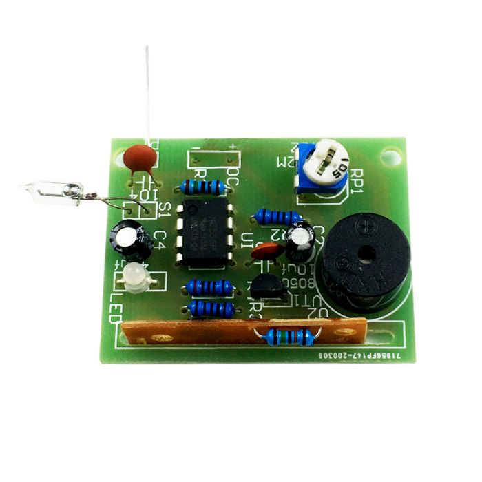
Working principle:
The touch vibration alarm consists of two parts: touch trigger circuit, vibration trigger circuit and alarm circuit. 555 time base circuit U1 forms a typical monostable working mode, whose transient time is determined by the values of RP1, R2 and C2. Normally, when the circuit is in steady state, the 555 time base circuit outputs a low level at pin 3, and the alarm chip does not alarm because there is no power supply. When the human hand touches the electrode piece M, the human body induction signal is injected into the 555 trigger terminal 2 pins by C1, or the vibration sensor S1 is instantly connected by vibration, which will make the U1 pin 2 appear instant low level, so that the 555 time base circuit flips into the transient state, the 3 pins suddenly change to high level, and the alarm chip is powered to sound the alarm. Once the transient time is over, the time base circuit flips back to the steady state and stops the alarm. LED is a two-color light-emitting diode, the green light is on after power on, as a power indicator, the red and green lights are on when the alarm is on, the overall orange-yellow color, the resistance value of the resistor R5 determines the speed of the alarm sound playback, generally take 180K-240K, pay attention to the installation of the chip before it is installed to the alarm chip board, the whole circuit DC3-6V can work .
DIY loose parts list.
PCB board 1
Mercury switch 1
KD9561 chip 1
150K resistor 1
10K resistor 1
1K resistor 2
10M resistor 1
3MM LED red 2
104 ceramic chip capacitor 2
10UF25V capacitor 2
8-pin chip holder 1
NE555 chip 1
105 blue and white potentiometer 1
8050 triode 1
Passive buzzer 1
No. 5 2 battery box 1
Soldering step 1: first solder the 150K resistor to the top of the music IC, 150K
put music IC front and back can be, while using the resistor excess
length of the pin cut down .
Next, solder the resistor above the module, the resistance is not polarized,
the resistance value depends on the color code or use multimeter to
measure the resistor value.
Next solder LED, electrolytic capacitors, transistors, LED. The electrolytic
capacitors are long lead positive, the negative capacitor on the board
silkscreen shading, transistors note the direction of separation.
Next
you can solder the rest of the devices, including the chip inserted when
you pay attention to the clear direction, the chip has a U port, pay
attention to look at .
-
Part No
-
Manufacturer
-
Stock No
2045-HA1
-
SKU No
263877
*Prices subject to change without notice. We reserve the right to limit quantities.
To purchase bulk quantities, Please contact our Sales Department
(+1-416-494-8999) or email shop@sayal.com
Documents & media will load when this tab is opened...